GPS Antenna Selection

The selection of a proper GPS antenna for a GPS tracking system is very important.  The main criteria to keep in mind when choosing a GPS antenna to work with your Raveon M7 series GPS transponder is:

  1. Amplified.  The antenna must have a build in RF amplifier that will operate off of 3.3V DC.  The power for the GPS antenna’s RF amplifier is feed down the center-conductor of the coax-cable going to the antenna. 
  2. SMA connector.  The RF connector for the GPS antenna is an SMA type connector. The cable will have a male connector on it, and the M7 has the female.
  3. Proper Mount.  GPS antennas are available in many different mounting configurations. 
  4. Proper Environment.  Some antennas are designed to be mounted on the roof of a car, others are suitable in salt-water environment and others are not.  Consult the manufacturer for information on temperature range and environmental restrictions. 

Raveon offers a number of GPS antennas for mobile GPS tracking.  They are shown on the website here:
http://ravtrack.com/gps-antenna-choices 

The simplest GPS antenna for vehicle mounting is Raveon’s RV-AN-GP2:

universal active gps antenna installation

Talley Electronics (http://www.talleycom.com/ ) distributes many different GPS antennas, and if you wish to order them from Raveon with your M7 transponder, please just add it to your order, and we will include it with your shipment. 

Talley’s GPS antennas are in their on-line catalog here: http://www.talleycom.com/store/category.jsp?cat=311&clr=1 

The MobileMark SM-1575-2C-WHT-180 GPS antenna is a rugged sealed amplified antenna suitable for most any application, even those with harsh environments. 

image

COCOM GPS Tracking Limits

The U.S. Department of Commerce requires that all exportable GPS products contain performance limitations so that they cannot be used in a manner that could threaten the security of the United States. The following limitations are implemented on the Trimble Copernicus receiver receiver.

Immediate access to satellite measurements and navigation results is disabled when the receiver’s velocity is computed to be greater than 1000 knots, or its altitude is computed to be above 18,000 meters. The receiver continuously resets until the COCOM situation is cleared.

If the Raveon GPS transponder will be used in aviation applications, the unit should be put into the AIR mode.  See the posting “gps-receiver-dynamics” for information about the AIR, LAND< and SEA modes.

GPS Receiver Dynamics

The GPS receiver in Raveon’s M7 and Atlas PL GPS transponder may be configured for different situations. By default it is configured for LAND operation.
Selecting the correct operating parameters has a significant impact on GPS receiver performance.  GPS receiver dynamics may be optimized for LAND, AIR, or SEA operation.
  
  LAND  = 1    Maximum speed the GPS will receive at is 233knots/268mph/430kmh.  Useful altitude from -2000 to +9000 meters.
  SEA = 2    Maximum speed the GPS will receive is not specified.  Useful altitude from -2000 to +9000 meters.
  AIR = 3   Maximum speed the GPS will receive at is 1000knots/1150mph/1800kmh.  Useful altitude from -2000 to +50,000 meters.
 
The default setting for the GPS receiver used in Raveon’s M7 series of GPS transponders and Atlas PL Transponders is LAND.
The default LAND operating parameters allow the receiver to perform well in most environments. Transponders with firmware version C12 or higher are able to view the GPS receiver’s configured dynamics, and change the dynamic mode between AIR, LAND, and SEA. Upon power up, the firmware reads the internal GPS receiver’s current configuration.

The user can optimize the internal GPS receiver in the transponder to a particular application.  If the receiver is then taken out of this environment, the specifically tuned receiver may not operate as well as a receiver with the default options.
The dynamics feature default setting is LAND mode, where the receiver assumes a moderate dynamic environment. In this case, the satellite search and re-acquisition routines are optimized for vehicle type environments. In SEA mode, the search and re-acquisition routines assume a low acceleration environment. In AIR mode, the search and reacquisition routines are optimized for high acceleration conditions. 

Reading the GPS Receiver Configuration

The GPS receiver configuration may be determined by using the GX command to show the overall configuration of the M7 or Atlas PL transponder. The “Dynamics” command will also return a string in the following format that indicates how the GPS receiver in the transponder is currently configured.   

MMM, EE.E, SS.S

 MMM: dynamic mode AIR, LAND, or SEA
 EE.E: Elevation Mask
 SS.S: Signal Mask  

Elevation Mask

This is the minimum elevation angle for satellites to be used in a solution output by the receiver. Satellites which are near the horizon are typically more difficult to track due to signal attenuation, and are also generally less accurate due to higher variability in the ionospheric and tropospheric corruption of the signal. When there are no obstructions, the receiver can generally track a satellite down to near the horizon. 

Signal Mask

This mask defines the minimum signal strength for a satellite used in a solution. There is some internal hysteresis on this threshold which allows brief excursions below the threshold if lock is maintained and the signal was previously above the mask.

Configuring the Dynamics

Use the DYNAMICS command to set or read the dynamics.  DYNAMICS with no parameter will return the configuration.  The following commands may be used to set the dynamics:

DYNAMICS 0    (factory default dynamic mode)
DYNAMICS 1    (LAND)
DYNAMICS 2    (SEA)
DYNAMICS 3    (AIR)

When issuing the DYNAMICS x command, give the GPS receiver a few seconds to execute it.  The M7’s firmware will also send a “flash save” command to the GPS receiver after the dynamics configuration is changed so that the change becomes permanent in the GPS receiver.  Upon power-up, the GPS receiver will use the new dyncamics setting. 

To verify the dynamics setting was saved, cycle power on the M7 or Atlas PL, enter the CONFIG mode, and enter the GX command to view the overall configuration of the device. The GPS receiver dynamics will be displayed.

Advanced GPS Receiver Configuration

To facilitate the advanced user, Raveon added a command “PASS” in the C12 firmware.  PASS will pass the parameter of the command to the internal GPS receiver in NMEA format. The GPS receiver used in the M7 transponder and ATLAS PL personal locator is a Trimble Copernicus II.  The technical manual for the Copernicus II contains details on how to configure it using NMEA type messages.  

For example, to set the GPS receiver to AIR mode, issue the following command while in the command mode.
    PASS $PTNLSCR,0.60,5.00,12.00,6.00,0.0000020,0,3,1

The command’s paramter is a NMEA formatted sentence without the * or the checksum.  The M7 or Atlas will append the * and the checksum to the sentence before sending it to the internal GPS receiver.  To set the dynamics, use the DYNAMICS x command, not the PASS command. The PASS command is provided to the advanced user who wished to reconfigure the receiver’s low-level configiruation paramters such as signal and elevation masks. 

If you change the GPS receiver’s configuration with the PASS command, do not forget to issue the save configuration command to the GPS reciever. The save command for the GPS receiver in the M7 and ATLAS PL is:
 PASS  $PTNLSRT,H,2,7,0

Battery Comparison for GPS Tracking Device

Overview

Many different types of batteries may be used with Raveon’s M7 series of GPS transponders.  This Technical Brief describes how well some common battery types will work with the M7 radios.

Actual battery life will vary based upon how often the M7 GPS transponder transmits, but the data in this Technical Brief may be used to predict the battery life of most configurations.

Test Setup

For the tests in this brief, a UHF GPS transponder, model RV-M7-UC-GX was configured in GPS mode 2 to transmit its position every 10 seconds.  In GPS mode 2, the radio’s receiver is on 100% of the time, and the current draw of the M7 was an average of 90mA.  The peak current draw was 2.1 amps for 68mS each time the M7 transmitted its GPS position.

Summary Data

Brand Type Recharge-able mAh Life
(RX on)
Life
(RX off)
Duracell Alkaline NO 1600 18 hours 36
Energizer Lithium NO 2500 28 hours 56
Lenmar NiMH Yes 1500 17 hours 34

Duracell Alkaline

These batteries are the common Duracel batteries found at most department stores.

Test Result Summary

Initial Voltage:                                   12.57 volts

Voltage at ½ discharge:                   10.2 volts

Usable life (hours)                           18 hours

Voltage drop when transmitting       2.4V  (1.1 ohm resistance)

Approximate mAh capacity             1600mAh

Discharge Curve

Transmit Transient

The plot below shows the dip in voltage as the transmitter turns on and off.


Summary

The Duracell is an OK battery to power the M7 transponder.  But its high internal resistance will reduce the RF power output after the first few hours of operation.  The DC to the radio should stay above 9V while transmitting for full power, above 8V for 3-4 watts.


Energizer Lithium

These batteries are the common Energizer Lithium batteries for cameras and digital electronics found at many department stores.

Test Result Summary

Initial Voltage:                                      12.1 volts  (14V for a few moments)

Voltage at ½ discharge:                      12.0 volts

Usable life (hours)                              28 hours

Voltage drop when transmitting          3.5V  (1.6 ohm resistance)

Approximate mAh capacity                2520mAh

Discharge Curve

Transmit Transient

The plot below shows the dip in voltage as the transmitter turns on and off.

Summary

Even though the internal resistance of the cell is higher than the alkaline, the Energizer Lithium is a good battery to power the M7 transponder.  Its high internal resistance will not reduce the RF power output because its voltage is fundamentally fairly high.  The DC to the radio should stay above 9V while transmitting for full power, above 8V for 3-4 watts, so the 3.5V dip means the radio will have full power at 12.5V, and 3-4 watts out at 11V DC at the battery pack.


Lenmar R2G NiMH pack, 2150mAh cells

These batteries are Nickel Metal Hydride rechargeable batteries.  They were fully charged before the test.

Test Result Summary

Initial Voltage:                                      11.0 volts

Voltage at ½ discharge:                      10.3volts

Usable life (hours)                              17 hours

Voltage drop when transmitting          2.0V  (.95 ohm resistance)

Approximate mAh capacity                1500mAh

Discharge Curve

Summary

These batteries should be a good power source for the M7 GX transponder.

The internal cell resistance is low, but the voltage is also low. The RF power output stayed at full power for most of the life of the battery, dropping to about 4 watts at the end of the battery life.  The double dip at end of live was due to the fact the radio keep working down to 6 volts (albeit with almost no RF output because the RF PA is off), and the batteries keep putting our very low voltage for another couple hours.


Raveon Technologies Corporation

990 Park Center Drive, C

Vista, CA 92081

sales@raveontech.com

760-727-8004

Antennas for a RavTrack vehicle tracking system

In a RavTrack system you will need antennas for vehicles, as well as base stations, and possibly repeaters if your particular system uses any repeaters.   Here will will discuss common antennas for all three uses.

The Raveon “GX” series of tracking transponders used in a RavTrack system can be configured to operate as a vehicle unit, a base station, or a repeater, all by software configuration.  Each GX transponder will have 2 antenna connections.  One is for a GPS antenna, and the other for a UHF antenna.

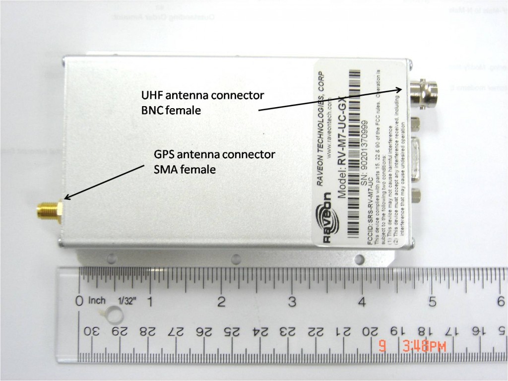
Here is a picture of the GX transponder in the standard enclosure.  Note that the GPS antenna connector is an SMA female, while the UHF connector is a BNC female.  They are at opposite ends of the transponder.
transponder-and-antenna-connectors

Note that if your transponder is the weatherproof version  the UHF connector is TNC female.  Transponders installed in vehicles for tracking purposes will require both a GPS antenna and a UHF antenna. We have a few antennas that are combination GPS and UHF antennas.  When these are offered the antenna cable(s) will terminate in 2 separate connections.

The GPS antenna receives the GPS satellite transmissions by which the transponder will determine its precise GPS location.  Note that the location is actually that of the antenna itself, which may be important to remember especially when dealing with large vehicles or other objects.

Once the location is determined the UHF antenna is required to allow transmission of the vehicle location.  The UHF antenna should be a “mobile” antenna chosen to match the proper transmission frequency of your system, as well as selected to best suit the type of vehicle.  The UHF antenna is almost always larger than the GPS antenna so size and styling can be important criteria.

Anther important criterion is the manner in which the antennas mount to the vehicle.    It is best to have the antennas as high up on the vehicles as practical, and generally speaking larger (UHF) antennas are typically better performers.  However an overly large antenna may not just be unsightly but prone to damage as well.  Some vehicles will be equipped with an “antenna bar” in order to mount the antennas.  As multiple antennas may posssibly compete with one another, it is best if a skilled RF technician is consulted or contracted to perform the installation.

Antenna mounts come in a variety of approaches of which the 3 most common are magnetic mount, through-hole mount, and flange mount.  The magnetic mount is most suitable for temporary installations, although the magnets are quite strong and the antennas may stay put even under challenging circumstances.  The through-hole mount is the sturdiest and most permanent, but requires a hole be drilled through the vehicle surface (or antenna bar).  The flange mount approach is typically used to grip the vehicle trunk lid, if this is available.  All of these mounts are available in “NMO” style where the UHF antenna physically threads on to the mount itself.  Here are some quick photos:

nmo-mag-mount5

NMO style magnetic mount

nmo-antenna-combines-to-mount6

Antenna threading onto NMO flange  mount.

thru-hole-nmo-mount4

Thorough-hole mount.

For more information on NMO mounts see the post “The versatile NMO antenna mount” in this section at:

http://ravtrack.com/GPStracking/2009/the-versatile-nmo-antenna-mount/

Oftten the GPS and/or UHF antenna will have a magnetic mount base or through-hole mount base incorporated as the antenna base.  Here is a photo of a combo GPS/UHF antenna with a through-hole base:

combo-antenna-thruhole

In some vehicle deployments the UHF antenna will not only broadcast location but will also receive transponder broadcasts from other fleet members.  This ability is fairly unigue to Ravtrack.

Once a location broadcast hits the air it is ready to be received by other fleet members but also by a base station or possibly a repeater.  Sometimes the base station is mounted on a mobile command vehicle, and special antenna considerations are in order.   However, typically the base station antenna is on top of a building, or an antenna tower.  Usually an omni-directional (all direction) antenna is used, as the vehicles can be broadcasting from many different locations.

The most common omni-directional base station antenna is made with a fiberglass sheath.  Here is a picture:

fiberglass-antenna

This sort of antenna typically mounts onto a pole or mast the customer provides.  Check to see if the actual mounting hardware is included with the antenna.

This antenna is also very effective for repeaters.  Sometimes, if a repeater is used the base station will use a directional antenna pointed at the repeater antenna.  Here is a picture of a Yagi style directional antenna used for this purpose:

yagi

Antennas can act as lightning attractors, so you may want to investigate lightning arrestors for some installations.

Here are some general rules if thumb when dealing with antenna installations::

Survey your area for best antenna locations

Use the largest antenna you can tolerate and afford

Make certain the antenna will work in your frequency

Determine your mounting and support early

Mount the antenna as high as practical

Try to keep the antenna cable short, and use good grade cabling

Take precautions against lightning and surge

Don’t forget signal cable and power for your transponders

Hire a skilled RF technician if at all possible